AVR I/O-web server with additional output pins via a 74hc595 port expander
ArticleCategory: [Choose a category, do not translate
this]
Hardware
AuthorImage:[Here we need a little image from you]
![[Photo of the Author]](../../common/images/Guido-S.gif)
TranslationInfo:[Author + translation history. mailto: or
http://homepage]
original in en Guido Socher
AboutTheAuthor:[A small biography about the author]
Guido likes Linux because it is a really good system to
develop your own hardware.
Abstract:[Here you write a little summary]
The tuxgraphics web server is not a normal web server.
It is an IO-web server. It reads sensor values or
IO-pins and it controls digital output lines or relays.
It is as well possible to have analog output lines providing
arbitary voltages between 0V and 3.3V by
using a R2R-ladder DAC.
Sometimes you want to have more digital output pins than the
microcontroller you are using provides. You can either
switch to a bigger microcontroller chip or use a 74hc595 port expander.
This article focuses on the 74hc595. Using multiple 74hc595 chips
you could in theory have an infinite amount of output lines on
a single ethernet board.
The advantage of the 74hc595 is that you save on
wires if you want to have the 8 additional output pins in a
different place. There is a serial connrection between
microcontroller and 74hc595. The cable lenght of that connection
should however not be longer than a meter (3ft).
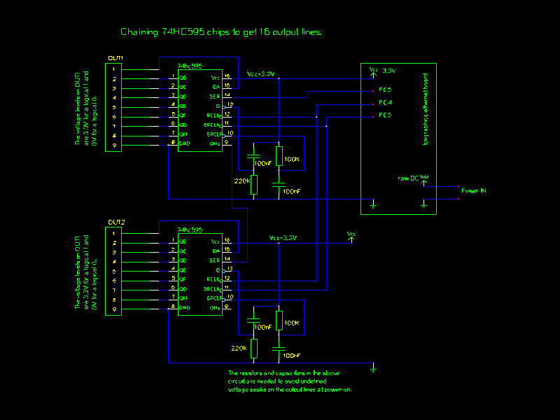
The 74hc595 chips can be chained to provide 16 bit output ports or more without
occupying any further output lines on the atmage.
For another article on IO-web servers which provide digital and analog input lines
together with digital output lines see "Using the
tuxgraphics embedded web server to control scientific equipment".
ArticleIllustration:[This is the title picture for your
article]
![[Illustration]](../../common/images2/article10081/ioweb-title.jpg)
ArticleBody:[The article body]
The 74hc595
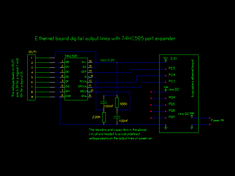
The 74hc595 consists internally of two 8-bit registers.
Those two registers are called shift register and storage
register. The eight output lines are connected to the
storage register. It is possible to fill the shift register in serial
bit by bit and move the content of the shift register into
the storage register with a single pulse on the RCK line (74hc595 pin 12).

[click on the picture for a PDF version]
|
Connecting the 74hc595 to the tuxgraphics AVR web server.
The software in the download section of this article provides as
well 4 traditional digital output lines directly at the atmega
chip on pins PD4, PD5, PD6 and PD7. They are as well
shown in the above drawing.
|
Power-on behavior
For many applications it is important to have a defined behaviour
during power on. You don't want to have random blinking or other
strange patterns even if you connect just LEDs to the output lines.
The 74hc595 has therefore a pin to clear the shift register (SRCLR, pin 10)
and to disable the output (G, pin 13) during power on.
Simple circuits hardwire those lines often to just Vcc and GND
and then you might get undefined pulses on the output at power on.
A good way to avoid undefined behaviour and not use any additional pins
on the microcontroller is to use a simple RC-timer. This RC-combination can
be used to hold the pins just for a few μS during power on and
then tie them to Vcc or GND respectively.
Chaining chips to get 16 or more output lines

[click on the picture for a PDF version]
|
Chaining two 74hc595 chips to get 16 digital output lines.
|
Note that the software which you find in the download
section is currently written only for 8 additional output lines.
If you want to chain two 74hc595 chips then you will have to
modify the software just a little bit.
The Software
There are two functions defined in main.c :
    init74595(void)

    set74595(uint8_t val)
You call init74595 at startup and then you can set
any of the output lines of the 74hc595 using set74595(val). A one in a certain bit position corresponds
to output-on and a zero corresponds output-off.
E.g 10000000 = dec 128 = hex 80 sets the output QH on
the 74hc595 to 3.3V.
If you want to change just one output and not set all at
once then just define a variable that holds the current output
bit pattern and use binary-AND or binary-OR to modify individual bits:
static uint8_t e74595val=0;
...

  i=3; // the third output pin (possible values 0..7)
  set74595(e74595val|(1<<i));// on
  ...

  i=3;
  set74595(e74595val&~(1<<i));// off
Connecting a relay
To switch on/off heavier loads it is a good idea to use a relay. It
offers a galvanic separation and protects the microcontroller.
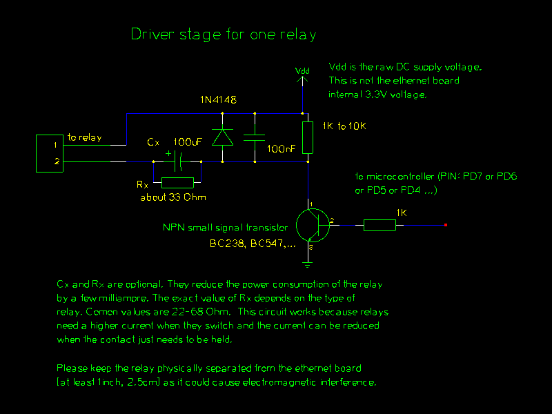
A relay itself causes however induced voltages at the driver when
the relay is switched off. For this a fly-back diode is absolutly needed.
I recommend to use the following driver stage for each relay that you want
to connect. The capacitor and resistor parallel to the fly-back diode supress additional noise that
might come in via the relay coil. You connect this driver to the
74hc595 output lines or the microcontroller.

[click for a PDF version]
|
A relay driver stage as needed for each relay.
|
Keep in mind that a normal relay consumes about 50-100mA at 6V. To build e.g
a circuit which controls 12 relays one would need a power supply that delivers 1.4A at
5V-6V. The tuxgraphics ethernet board consumes about 180mA.
You can lower the power consumption a bit using the capacitor Cx and the resistor Rx
as shown in the above circuit diagram. This works because relays need a higher
current to switch than they need to just hold the contacts together. This is because
they have a metal plate moving towards a magnet. When the plate is very close
to the magnet then the magnetic field is stronger and you can lower the current
a bit. The strength of a magnetic field is proportional to distance3 (distance to the power of three). The hold current is determinted by the resistor Rx. When the relay is switched
on then the 100μF capacitor is charged up and that causes the current peak
needed for the relay to switch.
Do not choose a too high value for Rx. The relay contact
need as well be pressed together a bit.
The user interface
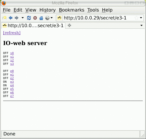
The user interface is a web page. The s0 to s3 are the standard output
lines on the microcontroller and the e0 to e7 are the eight additional
output lines available via the 74hc595 port expander.
To change a value from on to off or vice versa you just click on the name and
it toggles between on and off. There is a basic but convenient access
protection available. The URL contains a shared secret. It is set to "secret" in
the below screenshot.

|
Screenshot of the user interface.
|
References/Download

![[Photo of the Author]](../../common/images/Guido-S.gif)
![[Illustration]](../../common/images2/article10081/ioweb-title.jpg)


