http://tuxgraphics.org/electronics

A Digital DC Power Supply (programmable bench power supply unit), hardware version 3.0
![[Illustration]](../../common/images2/article10051/ddcp-title.jpg)
Abstract:
A good, reliable and easy to use bench power supply unit is probably the most
important and most used device in every electronic lab.
A proper electronically stabilized
bench power supply unit is an important but also expensive device.
Using a microcontroller based design we can build a power
supply which has a lot of extra features, is easy to build and very affordable.
The tuxgraphics digital DC power supply has been a very
successful product and this is now the third generation.
It is still based on the same idea as the first version but
comes with a number of good improvements.
_________________ _________________ _________________
|
Introduction
This bench power supply unit is less complex than most other circuits but
has a lot more features:
- The display shows the actual measurement values for voltage and current.
- The display shows the pre-set limits for voltage and current.
- Only standard components are used (no special chips).
- Only one power source is needed (no separate negative supply voltage for operational
amplifiers or control logic)
- You can control the power supply from a PC. You can read
current and voltages and you can set them with simple commands. This is very
useful for automated testing.
- A small button pad is available to directly enter the desired voltage and max.
current.
- It is really small but powerful.
How was it possible to remove components and add more features? The trick is to
move functionality which is normally based on analog components like operational
amplifiers into the microcontroller. In other words the complexity of the
software and algorithms is higher but hardware complexity is reduced. This
reduces the overall complexity for you as the software can just be copied.
The basic electrical design idea
A common misconception about a digital power supply is that people assume everything to be digital and don't understand how
this could possibly work with a circuit based on a microcontroller. We want
a clean and stable analog voltage as output and for this we use analog components. Only analog components are fast
enough to remove ripples due to load changes or any remaining 50/60Hz noise.
The emitter voltage on a transistor is related to the voltage on the base and not the input voltage on the collector. The main current flows however from C to E.
This simple circuit produces a clean DC voltage. It removes noise coming in through the collector pin and controls load changes on the emitter side.
In other words our digital power supply has a completely analog control system
for fast respose to load and voltage changes and we overlay
a second digital control system
for the more fancy features that a bench top power supply needs.
Let's remove the battery from that circuit and build the simplest possible electronically stabilized power supply.
It consists of 2 basic parts: a transistor and a reference voltage generated
with a Z-diode.
The output voltage of this circuit is Uref - 0.7V. The 0.7V is approximately
the voltage drop between B and E on the transistor. The Z-diode and
the resistor generate a reference voltage which is stable, even if the input
fluctuates and is noisy. The transistor is needed to handle higher currents
than the Z-diode and resistor alone can provide. In this configuration the
transistor just amplifies the current. The current which the resistor and
Z-diode need to provide is the output current divided by hfe (hef is a number
which you can lookup in the datasheet of the transistor).
What are the problems with this circuit?
- The transistor will die when there is a short circuit on the output.
- It provides only a fixed output voltage.
These are quite severe limitations which make this circuit unusable but this
circuit is
still the basic building block of all electronically regulated power supplies.
To overcome those problems you need
some "intelligence" which will regulate the
current on the output and a variable reference voltage. That's all (... and
this makes the circuit much more complex).
For the last few decades people have used operational amplifiers to provide this
intelligence. Operational amplifiers can basically be used as analog calculators to
add, subtract, multiply or logically "or" voltages and currents.
Today microcontrollers are so fast that all this can easily be done in software.
The beauty is that you get as a side effect a voltmeter and an amperemeter
for free. The control loop in the microcontrollers has to know voltage and
current values anyhow. You just need to display them.
What we need from the microcontroller are:
- A AD-converter to measure voltage
and current all the time
- A DA-converter to drive our power transistor (provide the
reference voltage)
The problem is that the DA-converter needs to be very fast. If there is a short
circuit detected on the output then we must immediately reduce the voltage
on the basis of the transistor otherwise it will die. Fast means within
milliseconds (as fast as an operational amplifier).
The ATmega8 has an AD-converter which is more than fast enough but it has
at first glance no DA-converter. It is possible to use pulse width modulation (PWM)
and an analog low pass filter to get an DA-converter but PWM alone is much too slow
to implement the short circuit protection in software. How to build a fast
DA-converter?
The R-2R ladder
There are many ways to build a digital to analog converter but we need a
fast and cheap one which can easily interface to our microcontroller.
There is a DA-converter circuit known as "R-2R ladder". It consists of resistors
and switches only. There are two types of resistors. One with the value R and one
with twice the value of R.
The above shows a 3 bit R2R-DA-converter. The control logic moves the switches
between GND and Vcc. A digital "one" connects the switch to Vcc and a digital
"zero"
to GND. What does this circuit do? It provides voltages in steps of Vcc/8.
In general the output voltage is Z * (Vcc/(Zmax+1) where Z is the digital
number. In the case of a 3 bit AD converter this is: 0-7.
The inner resistance of the circuit as seen from the output is R.
Instead of using separate switches we can connect the R-2R ladder to the
microcontroller output lines.
Generating a variable DC signal with PWM (pulse width modulation)
Puls width modulation is a method
where you generate pulses and run them thru a low pass filter
with a cut off frequency much lower than the pulse frequency.
This results in a DC signal and the voltage depends on the width
of those pulses.
Using PWM to generate a variable DC voltage.
The atmega8 provides in hardware
16bit PWM. That is: you could theoretically have a 16bit DAC with
just very few components.
In order get a true DC signal out of a PWM signal one has to average
it out using a filter and that can be a problem at high resolutions.
The more accuracy you have the lower the frequency of the PWM signal.
This again means you need big capacitors and the response time is
very slow. The first
and second generation of the digital DC power supply had a 10bit
R2R-ladder DAC. That is: the output could be set in 1024 step.
If you run the atmega at 8MHz and use a 10bit PWM DAC then
the PWM signal pulses have a frequency of 8MHz/1024=7.8KHz. To
get a somewhat good DC signal out of this you need to filter it
with a second order low pass filter of 700Hz or less.
You can imagine what happens if you use 16bit PWM. 8MHz/65536=122Hz.
One would need a 12Hz low pass.
Combining R2R-ladder and PWM
It is possible to combine the idea of the PWM and the R2R-ladder.
In this design we will use a 7bit R2R-ladder combined with a 5bit
PWM signal. With a 8MHz system clock and 5bit resolution we will get
a 250KHz signal. 250KHz can even be converted with small capacitors
into a DC signal.
The original version of the tuxgraphics digital DC power supply had
a 10bit DAC based on the R2R ladder. In this new design we use
R2R-ladder and PWM with a total resolution of 12bit.
Oversampling
At the expense of some processing time one can increase the resolution
of an analog to digital converter (ADC). This is called oversampling.
Four fold oversampling results in double resolution. That is: 4 consecutive
samples can be used to get twice as many steps on the ADC.
The theory behind oversampling is explained in the PDF document which
you can find at the end of this article.
We use
oversampling for the voltage control loop. For the current control loop we use
the original resolution of the ADC as fast response times are here more
important than resolution.
A more detailed design
So here is now a more detailed design of the above circuit.
A few technical details are still missing:
- The DAC (digital to analog converter) can not provide the current to drive
the power transistor
- The microcontroller operates at 5V so the maximum output of the DAC is 5V
which means that the maximum output voltage behind the power transistor will be
5-0.7=4.3V .
To fix this we must add amplifiers for current and voltage.
Adding an amplifier stage to the DAC
When adding amplifiers we must keep in mind that those must work with large
signals. Most amplifier designs (e.g for audio) are done under the assumption
that the signals will be small compared to the supply voltage. So forget all the
classic books about transistor amplifier design.
We could use operational amplifiers but those would require extra positive and
negative supply voltages which we want to avoid.
There is also the additional requirement that the amplifier must go from zero
voltage to a stable state without oscillating.
In words there must not be any short oscillation or output peek when you switch
on the power supply.
The below circuit shows an amplifier stage which is
suitable for this purpose.
We start with the power transistor. We use a BD245 (Q1). According to the datasheet
this transistor has
a hfe=20 at 3A output. It will therefore draw about 150mA on the basis.
To amplify the current we use
a configuration known as "Darlington transistor". For this we put a medium power
transistor
in front. Those have typically a hfe value of 50-100. This will reduce the current needed to
less than 3mA (150mA / 50).
3mA are manageable with small signal transistors like BC547/BC557. Those
small signal transistors are then very good for building a voltage amplifier.
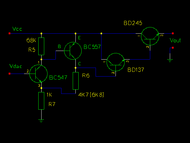
For 30V output we must at least amplify the 5V from the DAC by a factor of 6.
For this we combine a PNP and an NPN transistor as shown above. The voltage amplification
factor of this circuit is:
Vampl= (R6 + R7)/R7
The power supply shall be
available in 2 version: Max 30 output and max 22V output. A combination of 1K
and 6.8K gives a factor of 7.8 which is good for the 30V version and has some
room for possible losses due to higher currents (our formula is linear. The reality
is non-linear). For the 22V
version we use 1K and 4.7K.
The inner resistance of the circuit as seen on the Basis of BC547 is:
Rin=hfe1 * S1 * R7 * R5 = 100 * 50 * 1K * 47K = 235 MOhm

- hfe is about 100 to 200 for a BC547 transistor
- S is the slope of the amplification curve of a transistor and is
 about 50 [unit=1/Ohm]
This is more than high enough for the connection to our DAC which has a inner resistance of 5K.
The inner equivalent output resistance is:
Rout= (R6 + R7) / (S1 + S2 * R5 * R7) = about 2 Ohm
Low enough to drive the following transistor Q2.
R5 ties the basis of BC557 to
the emitter which means "off" for the transistor until the DAC and BC547 come up.
R7 and R6 tie the Basis of Q2 initially to ground which shuts the output
darlington stage down.
In other words every component in this amplifier stage is initially off.
This means we will not get from those transistors any oscillations or output
peeks at power on or power off. A very important point. I have seen expensive
industrial power supplies which produced a voltage peek at power off. Such a
power supply is definitely to be avoided as it can easily kill sensitive
circuits.
The limits
From previous experience I know that some readers would like to
"customize" the circuit a bit. Here is a list of hardware limits
and how to overcome them:
BD245B: 10A 80W. The 80W are however at a temperature of 25'C
        In other words add a safety margin and calculate with 60W-70W:
        (Max input voltage * Max current) < 65W

        You can add a second BD245B to go up to 120W. To ensure
        that the current distributes equally add a 0.22 Ohm resistor
        into the Emitter line of each BD245B.
        The same circuit and board can be used. Mount the transistors
        on a proper aluminum cooler and connect them with short
        wires to the board. The amplifier can drive a second power transistor
        (that's the maximum) but you might need to adjust the
        amplification factor.

Current measurement shunt:
        We use a 0.75 Ohm resistor with 6W. This is good enough
        for about 2.5A of output (Iout^2 * 0.75 <= 6W). Use a resistor
        with more watts for higher currents.
Power sources
You can either use a transformer, rectifier and big capacitors or
you can try to get a 32/24V laptop power supply.
I went for the later option. Those laptop power supply "bricks" are
sometimes sold very cheap (over stock) and some of them provide
70W at 24V or even 32V DC.
Most people will probably go for a transformer because those are
very easy to get.
22V 2.5A version:  you need a 18V 3A transformer, a rectifier
                   and a 2200uF or 3300uF capacitor. (reason: 18 * 1.4 = 25V)

30V 2A version:    you need a 24V 2.5A transformer, a rectifier and
                   a 2200uF or 3300uF  capacitor. (reason: 24 * 1.4 = 33.6V)

It does not harm to buy a transformer which can provide more ampere.

A power diodes bridge with 4 diodes which are specified for a
low voltage drop (e.g BYV29-500) gives a good
rectifier.
You can also
use a "heavier" transformer.
Check your circuit for proper insulation. Make sure that it is not possible to
touch any part that may carry 110V/230V even when the case is open.
Connect all metal parts of the chassis to earth (not to GND of the circuit).
Transformers and laptop power supply bricks
If you want to use two or more power supplies in a chain
to get positive and negative voltages for your circuit then
it is important that the transformer is really insulated. Be careful
with laptop power supply bricks. They are nice and small but some of them
may connect the minus pin on the output to the earth pin on the input.
This will then cause a short ciruit via the earth wire if you use
two power supplies in a chain.
Other voltages and current limits
The two provided configurations are 22V 2.5A and 30V 2A. If you want
to build a version with other (lower) output voltages or current limits
then just edit the hardware_settings.h file.
Example: To build a 18V 2.5A version you just edit the hardware_settings.h
file and change the maximum output voltage to 18V.
You can then use a 20V 2.5A power source.
Example: To build a 18V 1.5A version you just edit the hardware_settings.h
file and change the maximum output voltage to 18V and the max. current to
1.5A.
You can then use a 20V 1.5A power source.
Testing
The last component to solder to the board should be the microcontroller.
Before you insert it I would recommend to do some basic hardware tests:
Test1:
Connect some power supply (at least 10V) to the power input of the circuit and
check that you get 5V DC behind the voltage regulator.
Test2: Measure the output voltage. It should be 0V (or near zero, e.g 0.15V, and
it will go to zero if you put a "load" of 2K to 5K on the output.)
Test3: Solder the microcontroller to the board and load the LCD test software by running the
commands in the directory of the unpacked digitaldcpower tar.gz package.
make test_lcd.hex
make load_test_lcd
You should see "LCD works" on the display.
Now you can load the final software.
A word of warning for further testing with the final software: Be careful with short
circuits until you have tested the current limitation function. A save way to
test the current limitation is to use a low Ohm resistor, e.g a car bulb.
Set a low current limit, e.g 30mA at 10V. You should see the voltage
go down immediately
to almost zero once you connect the bulb on the output. There is still a fault
in the circuit if it does not go down. The car bulb will protect the power
supply circuit even if there is a fault as it is not a full short circuit.
The software
This section will give you insights as to how the software
works and you can use the knowledge to do modifications.
However be aware that the short circuit protection is also only
software. If you make a mistake somewhere then this protection
may not work. If you cause then a short circuit on the output
your hardware may go off in a cloud of smoke. To avoid this
you should use a 12V car bulb (see above) to test the short circuit
protection.
Now a bit about the software structure.
First look at the main program (file main.c, download at the end of this
article) you will see
that there are only a few lines of initialization code executed
at power on and then the software enters an endless loop.
There are really 2 endless loops in this software.
One is the main loop ("while(1){ ...}" in file main.c) and the
other one is the periodic interrupt from the Analog the Digital
Converter (function "ISR(ADC_vect){...}" in file analog.c).
During initialization the interrupt is configured to execute every
104μ Sec. All functions and code that is executed runs in
the context of one of those tasks (task the name for a process
or thread of execution in a real time OS, so I use this word here even if
there is no OS).
![[priorities]](../../common/images2/article10051/tasks.gif)
The interrupt task can stop the execution of the main loop at
any time. It will then execute without being interrupted and
then execution continues again in the main loop at the place
where it was interrupted. This has two consequences:
- The code in the interrupt must not be too long as it must
finish before the next interrupt comes. What counts here are
the amount of instructions in machine code. A mathematical
formula, which can be written as just one line of C-code may
result in hundreds of lines of machine code.
- Variables that you share between interrupt code and code
in the main task may suddenly change in the middle of
execution.
All this means that complex things like updating of the
display, checking of push buttons, conversion of ampere and
volt values to internal units etc ... must be done in the main
task. In the interrupt we execute only things that are time
critical: Current and voltage control, overload protection and
setting of the DAC. To avoid complex mathematics all
calculations in the interrupt are done in ADC units. That is
the same units that the ADC produces (integer values from
0...1023 for current and 0..2047 for voltages).
This is the basic idea of the software. I will also explain
what you find in which files and then you should be able to
understand the code (given that you are familiar with C).
Software: Which file contains what
main.c -- this file contains the main program. All initialization is
         done from here.here.  The main loop is also implemented here.

analog.c -- the analog to digital converter and everything that
         runs in the context of the interrupt task can be found here.

dac.c -- the digital to analog converter. Initialized from ddcp.c but
         used only from analog.c

kbd.c -- the keyboard code

lcd.c -- the LCD driver. This is a special version which will not need
         the RW pin of the display. It uses instead an internal timer
         which should be long enough for the display to finish its task.
Loading and using the software
To load the software into a microcontroller you need a programmer such
as the avrusb500. You can download the ziped software archives
at the end of the article.
Edit the file hardware_settings.h and adjust it according to the hardware.
Here you can also do calibrations of voltmeter and amperemeter. The file
is well commented.
gedit hardware_settings.h
Connect the programmer cable and power on the circuit.
Then run:
make fuse

This will set the clock frequency of the microcontroller to 8MHz. The
software is designed for this frequency.

make

This will compile the software.

make load

This will load the software.
Control of the power supply unit from any PC (Win, Linux, Mac,...)
This power supply can be controlled by 5 buttons on the front pannel
or via a USB connection from a PC.
The power supply to USB interface is an optional add-on card.
![[ddcp to usb]](../../common/images2/article10051/usb-interface.jpg)
Digital power supply USB interface with galvanic separation.
Note: we finally decided to use a USB-B socket. The power
supply shown in the title image of this article has a different
connector as it was built before that decision was made.
The card offers galvanic separation
such that you can use this power supply relative to
any reference point (e.g build two power supply units and use
one as negative and one as positive power supply).
Galvanic separation is achieved buy using two opto-coupler chips.
The information is transmitted with light pulses inside the chip
but there is no electrical connection between the receiving and
transmitting side.
The power supply shows then up as a virtual com-port on your computer
and you can connect to it with any serial terminal.
HyperTerminal is a popular windows serial terminal software
but it is a bit complicated to use. I prefer putty (http://www.chiark.greenend.org.uk/~sgtatham/putty/). For Linux I can recommend
picocom
(http://code.google.com/p/picocom/) It is simple and straight forward to use. Just run the command
"picocom -l -b 9600 /dev/ttyUSB0" and to disconnect you type Crtl-a Crtl-x.
The port settings are as follows:
    baudrate   : 9600
    parity     : none
    flowcontrol: none
    stopbits   : 1
    databits   : 8
![[serial terminal]](../../common/images2/article10051/screenshot-cmd-interface.gif)
Command interface for the power supply
The power supply accepts simple commands like "u=.." to set the voltage
or "i=.." to set the current. There is as well a "help" command which
explains all commands and the syntax. The command prompt shows the
same information that can be seen on the LCD display of the power supply.
You can control the digital power supply by commands. A number
of commands are provided for this purpose. They are at the moment
available for Linux, Mac and Windows:
ddcp-script-ttyinit   - initialize the COM port (run this once at
                        at the beginning)
ddcp-script-getval    - get current values (same as you see on the LCD)
ddcp-script-setval    - send a command to the power supply
With this you can write a shell script or batch file
to control the power supply or print current values for current and voltage:
#!/bin/sh
dev="/dev/ttyUSB1"
# initialize the com port
ddcp-script-ttyinit "$dev"
#
echo "current settings are:"
ddcp-script-getval "$dev"
#
echo "setting voltage to 3.3 V"
ddcp-script-setval "u=33" "$dev"
#
echo "wait a bit, it takes a moment for the display values"
echo "to adjust as they are polled in intervals by the avr software."
sleep 1
echo "the new settings are:"
ddcp-script-getval "$dev"
The buttons
The power supply has 4 button for local control of voltage and max. current.
The 5-th button is to store the settings permanently in an eeprom such that
it will come up with identical settings the next time you power it on.
![[buttons]](../../common/images2/article10051/buttons.gif)
The local control button pad.
With U+ you can increase the voltage and with U- you decrease it. When you
hold the button then it will step and after a while "run" faster to make
it easy to change the voltage in large steps. The I+ and I- buttons work
the same way.
The display
This is how the display looks like:
![[display]](../../common/images2/article10051/display.png)
The fields in the LCD display area. The real measured
values and the set values are always shown at the same time.
The arrow on the right indicates that currently the configured voltage
is the limiting factor. Should a short circuit occur on the output or
the connected device draws more current then the arrow will flip to the
bottom line and indicate that the configured max. current has become the limiting
factor.
Some pictures and ideas
Here are some pictures from the power supplys which I have build.
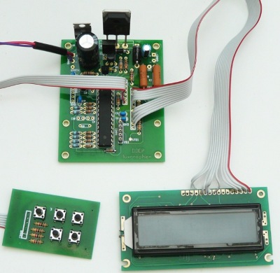
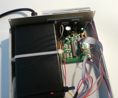
The circuit. Very small but with more features and more powerful than many
other power supply circuits.
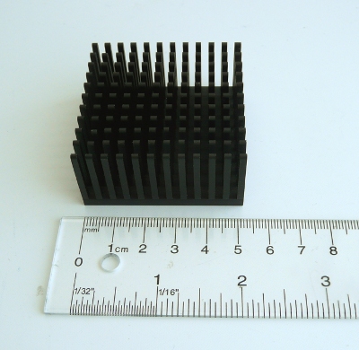
An old Pentium5 aluminium cooler is a good choice for this power supply. It is compact
and very efficient. A cooler that provides about 1K/W is sufficient. You might as well
consider to under dimension it a bit. It will normally be very rare that you operate it permanently
at maximum current with a low output voltage.
Installing the components in a case
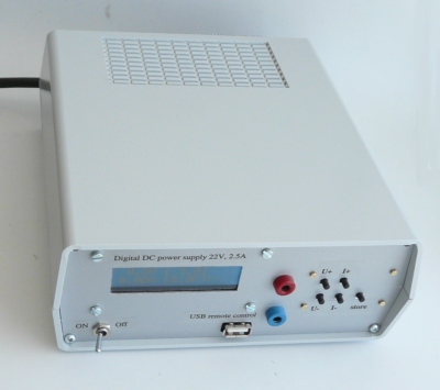
The final power supply unit.
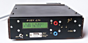
The final power supply unit. -With a green display-
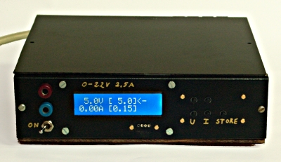
... and with a blue display in a different case.
Blue displays are bit difficult to
photograph.
It looks even better in reality than here on the photo.
|
Have fun! I am sure you will like this power supply unit. I use it a lot
and every day.
References/Download
© Guido Socher, tuxgraphics.org
2015-02-25, generated by tuxgrparser version 2.57