Using the "Mini 3 digit display"
ArticleCategory: [Choose a category, do not translate
this]
Hardware
AuthorImage:[Here we need a little image from you]
![[Photo of the Author]](../../common/images/Guido-S.gif)
TranslationInfo:[Author + translation history. mailto: or
http://homepage]
original in en Guido Socher
AboutTheAuthor:[A small biography about the author]
Guido likes Linux because it is a really good system to
develop your own hardware.
Abstract:[Here you write a little summary]
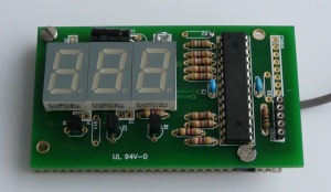
The Mini 3 digit display
aka "DVM-module" (digital voltmeter module) can easily be tuned and
modified because you have control over the firmware. The key advantages
of this module are:
- can be freely programmed and calibrated
- one can power the module from the same power source as
the power of the circuit were you want to take the measurement.
- it's not only a voltmeter
Let's experiment a bit with this module.
ArticleIllustration:[This is the title picture for your
article]
![[Illustration]](../../common/images2/article09031/dvm-module.jpg)
ArticleBody:[The article body]
Not only 2.56V and higher
The internal reference voltage in the atmega8 microcontroller is 2.56V. Just by
adding 2 resistors one can measure any voltage higher than 2.56V. How can I
measure smaller voltages?
It's simple: just add an amplifier. The problem is only the power of supply
for the amplifier circuit. A lot operational amplifiers need positive and
negative voltages of e.g +/- 15V. That is not really convenient for our
application. We need something that works with about 5V (same as the atmega8).
The TS272 or TLC272 is
a very good option. It has a very high input impedance of typically 1GOhm.
You can use this therefore for true voltage measurements e.g on electrochemical
cells.
DC pre-amplifier for measuring 0-500mV. The resistor R3 protects the op-amp.
The combination of resistors in the above example gives you a measurement range
from 0-500mV with 1mV resolution. VDIV has to be adjusted in the file analog.c
to calibrate the amplification factor into the software:
#define VDIV 1.955
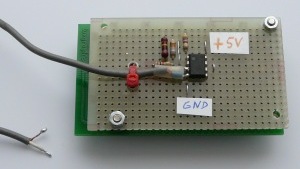
It is easy to add this amplifier by adding a dot matrix board on the back of
the 3 digit display module:
You can build a compact "sandwich" by adding the amplifier on the back.
Note that a voltmeter with more than 1GOhm input impedance is very sensitive to
electric fields and grabs any voltage just out of the air. I recommend to use
a shielded cable or to lower the input impedance by adding a resistor in parallel
to the input (Ri in the above schematic).
Measuring current
To measure a current you just need to measure the voltage over a low ohm
resistor (e.g 1 Ohm, 5W). A current of 2A would then result in a voltage
drop of 2V. By changing the VDIV calibration constant in the file analog.c you
can calibrate the circuit as needed. If a voltage drop of 2V is not acceptable
then just use 0.1 Ohm and add an amplifier.
You can then adjust it to your needs by using the above amplifier circuit with a different amplification factor (resistors R1, R5 and R2).
The calibration can be done by using a reference ampere meter and modifying
VDIV in analog.c
The DVM module measures always voltages between GND and the ADC0 pin on
the atmega8 microcontroller. This means that the low ohm resistor needs
to be connected on one side to GND.
Counting events
So far we have use mostly the analog to digital conversion capability of the
atmega8 microcontroller. This microcontroller has however also digital input
lines. Here is a little counter:
A digital counter
The counter software is included in the source code software package from version mini-voltmeter-0.4 and up.
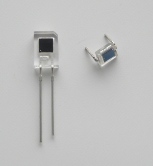
Photodiodes:
left: Everlight PD638C, right: BPW34
The longer wire or the top layer of the chip is Anode (marked with "A" in the circuit diagram). |
Counting objects with a photoelectric light barrier
The counter does not have to be connected to a mechanical switch. It can also
be connected to a "light beam" and count objects interrupting that beam. For this
we add a photodiode and a transistor which acts as amplifier. A small laser
pointer pen makes a very good light beam and works even over long distances. You do
not have to power the laser-pointer from a battery. Just open it take out the
battery and connect
it to a DC power supply. You can power it from the same 5V that the counter
circuit is powered from. In this case you need to add a resistor in series with
the laser pointer. A laser pointer that used 2x1.5V batteries will probably need a 220 Ohm
resistor in series when connected to 5V.
The photo diode needs to be placed in a small dark plastic tube to shield
it from day light. You can take a ball-pen apart to get a small plastic tube.
Counting objects with a photoelectric light barrier
Photodiodes are most sensitive to infrared light. A laser pointer is the best
light source for long distances (1m to 200m). For shorter distances you can also
use an Infrared-LED (invisible to humans).
Timer (1-999 sec)
This application is quite similar to the counter except that we generate the
pulses via the atmega8 internal clock. The circuit has no crystal but uses
the internal clock. This internal clock is not calibrated but you can calibrate the timer by adjusting the line
#define CLOCKDIV 223
in file timer.c. The internal clock is stable enough for a short term timer.
The circuit has several inputs to start and stop the timer as
well as a button to reset it. You can use a button connected to pin PB1. Clicking once starts
the timer and clicking a second time stops it. You can use the individual
start stop input lines or buttons.
A digital timer
The timer software is included in the source code software package from version mini-voltmeter-0.5 and up.
A calibrated digital thermometer
 The ds18s20 from maxim dallas semiconductors is a calibrated digital temperature sensor.
It looks like a small transistor. The pinout description is shown on the right.
The ds18s20 from maxim dallas semiconductors is a calibrated digital temperature sensor.
It looks like a small transistor. The pinout description is shown on the right.
We connect it to this "Mini 3 digit display" and we have a very reliable and
accurate digital thermometer. This thermometer source code is included in mini-voltmeter-0.9
and higher and you find it in the subdirectory therm. There is also
a pre-compiled hex file ( main_therm_pre.hex ) suitable for loading into
the atmega8 chip.
The sensor can be connected without any additional components and you can
have a couple of meters cable between sensor and circuit board.
The microcontroller pin PC1 can be used to change the display units.
If PC1 is left open then it displays 'C. If connected to GND then it displays
'F. If you connect a little switch then you can change the units at run time.
The display shows full degrees (no decimal point).
A calibrated digital thermometer
Your own formula and your own application
This display can be used to convert any voltages into some kind of number and
display it. To make your life easier we provided from version mini-voltmeter-0.7
on-wards a custom_formula_example.c file. It shows how to read out a
hall sensor and display a value based on a custom formula. It uses floating
point math and you can use any type of formula. Open custom_formula_example.c
and look at the code. It has towards the end of the file a long explanation.
In version mini-voltmeter-0.8 a second custom formula example was added. It will
display -58'F at 0.73V input and 347'F at 2.32V input. It is an application
developed for a customer who wanted to display the values of a sensor in his
car.
From this revision 0.8 onward
it is possible to display negative and positive numbers as long as they are
in the range from -99 to 999.
References/Download