home |
electronics |
toolbox |
science club |
tuxtalk |
photos |
e-cards |
online-shop

Content:
By Guido Socher
<guido_at_tuxgraphics.org>
|
A simple digital thermometer
![[Illustration]](../../common/images2/article07051/I2Ctemp-20074-title.jpg)
Abstract:
This is an
update of two articles which I wrote in 2005 about a small
digital thermometer. The circuit seems to be very popular because
it is so simple and still has a very useful and practical
application. It is the perfect circuit to get started with AVR
microcontrollers.
This updated article replaces the articles from 2005 and
simplifies the software as well as the hardware. The original
documents from 2005 are linked at the end of this article in case
you still need them.
This thermometer can be used as a standalone thermometer with LCD
display or it can be read out with a PC running Linux, Windows,
MacOSX or solaris. BSD Unix and others are probably also possible
to use for reading the temperatures. No special drivers are needed.
The hardware described here can be ordered from http://shop.tuxgraphics.org
_________________ _________________ _________________
|
Introduction
When you use such an advanced device as a
microcontroller to measure analog or digital signals then you
want of course interfaces to evaluate the data or send commands
to the microcontroller. In all the articles presented here in the
past we always used rs232 communication with the UART that is
included in the microcontroller. The problem is that this
requires an additional MAX232 chip, 4 extra capacitors and an
external crystal osciallator for the microcontroller. In any case
it is a lot of extra parts..... and we can avoid them!
We go here for connectivity via I2C because it is reliable and
really easy to build. The amount of data to transfer between PC
and microcontroller is very small (just a few bytes). Speed is
therefore no issue at all.
The LCD display is optional. The software is written such that it
is identical for the hardware with and without the LCD display.
What is I2C?
I2C (prounouce "eye-square-see") is a
two-wire bidirectional communication interface. It was invented
by Philips and they have protected this name. This is why other
manufacturers use a different name for the same protocol. Atmel
calls I2C "two wire interface" (TWI).
Many of you might already be using I2C on their PCs without
knowing it. All modern motherboards have an I2C bus to read
temperatures, fan speed, information about available memory....
all kind of hardware information. This I2C bus is unfortunately
not available on the outside of the PC (there is no physical
connector). Therefore we will have to use something else.
How I2C/TWI works
The datasheet of the Atmega8 (see
references) has actually a very detailed description starting on
page 160. I will therefore present here just an overview. After
this overview you will be able to understand the description in
the datasheet.
On the I2C bus you always have one master and one or several
slave devices. The master is the device that initiates the
communication and controls the clock. The two wires of this bus
are called SDA (data line) and SCL (clock line). Each of the
devices on the bus must be powered independently (same as with
traditional rs232 communication). The two lines of the bus are
normally connected via 4.7K pullup resistors to logically "High"
(+5V for 5V ICs). This gives an electrical "or" connection
between all the devices. A device just puls a line to GND when it
wants to transmit a 0 or leaves it "High" when it sends a 1.
The master starts a communication by sending a pattern called
"start condition" and then addresses the device it wants to talk
to. Each device on the bus has a 7 bit unique address. After that
the master sends a bit which indicates if it wants to read or
write data. The slave will now acknowledge that it has understood
the master by sending an ack-bit. In other words we have now seen
9 bits of data on the bus (7 address bits + read_bit + ack-bit):
| start | 7-bit slave adr | read_data bit | wait for ack | ... data comes here
What's next?
Next we can receive or transmit data. Data is always a multiple
of 8 bits (1 byte) and must be acknowledged by an ack-bit. In
other words we will always see 9-bit packets on the bus. When the
communication is over then the master must transmit a "stop
condition". In other words the master must know how much data
will come when it reads data from a slave. This is however not a
problem since you can transmit this information inside the user
protocol. We will e.g use the zero byte at the end of a string to
indicate that there is no more data.
The data on the SDA wire is valid while the SCL is 1. Like this:
SDA H -\       /---\     /---\          /---\
    L   \-----/     \---/     \--------/     \------....

SCL H ----\     /-\       /-\     /-\    /-\    /-\
    L      \---/   \-----/   \---/   \--/   \--/   \-....


  | START |      1 |       1 |     0 |    1 |    0 |
One of the best things about this protocol is that you do not
need a precise and synchronous clock signal. The protocol does
still work when there is a little bit jitter in the clock
signal.
Exactly this property makes it possible to implement the I2C
protocol in a user space application without the need for a
kernel driver or special hardware (like a UART). Cool isn't it?
The plan
As said before we cannot use the PCs internal
I2C bus but we can use any external interface where we can send
and receive individual data bits. We will just use the RS232
hardware interface of our PC. In other words our communication
interface is RS232 but we save the MAX232 hardware, capacitors,
etc...
A USB to RS232 converter can be used if you PC does not have a
RS232 port.
The LCD display is optional but if you add one then you can use
this as well as a standalone thermometer with local LCD display.
The temperature sensor
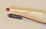
NTCs are small and cheap with reasonable accuracy |
It is possible to get already
calibrated temperature sensors (some of which talk I2C ;-) but
they are quite expensive. NTCs are cheaper and almost as good
even without individual calibration. If you calibrate them a bit
then it is possible to achieve accuracy behind the decimal
point.
One problem with NTCs is that they are non linear. It is however
just a matter of semiconductor physics to find the right formula
to correct the non linear curve. The microcontroller is a little
computer therefore mathematical operations are not a problem.
NTCs are temperature dependent resistors. The value R of the NTC
at a given temperature is:
 T or Tc is the temperature value that we are looking
for. Rn is the resistive value of the NTC at 25'C. You can buy
4k7, 10K, ... NTCs so Rn is this value.
T or Tc is the temperature value that we are looking
for. Rn is the resistive value of the NTC at 25'C. You can buy
4k7, 10K, ... NTCs so Rn is this value.
The circuit
Most of the components are actually for the
power supply part. We need a stable reference voltage for the
NTCs otherwise the temperature readings will not be accurate.
There is also an LED connected. It does not cost much and is
really useful for basic debugging and initial hardware test. The
hardware test program test-led.c just causes the LED to blink and
is part of the software package (see download at the end of this
article).
The analog to digital converter in the microcontroller is used to
measure the voltage on the NTC which will then be converted into
a temperature value.
The Atmega8 has two options on what is used as a reference
voltage for the analog to digital converter. It can use either
the 5V (AVcc) or an internal 2.56V reference. For the inside
temperatures we will not need a temperature range which is as big
as for the outside sensor. +10'C to +40'C should normally be
sufficient. We can therefore use the 2.56V reference when we
measure the indoor sensor. This gives very high accuracy as the
1024 possible digital values are then spread over only 0-2.56V
that is we get a resolution of 2.5mV (more accurate than most
digital voltmeters!).
The CD-pin on the RS232 is an input line and it is connected to
SDA on the I2C bus. We use it to read data from the
microcontroller. DTR and RTS are output lines. When the PC puts
data-bits on the SDA line then it just toggles DTR. The
I2C-master (here the linux PC) controls the SCL (clock) line. In
other words the clock line is an output line on the rs232.
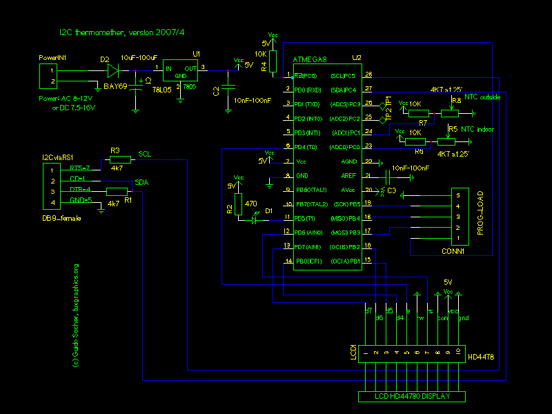
Circuit diagram. Click on the diagram for a more detailed view
in PDF.
Note: The LCD display is optional. Just connect nothing if you do not want
to use the LCD display.
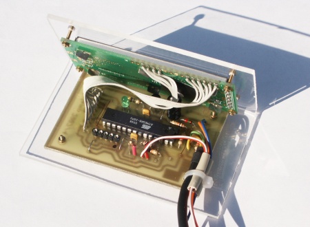
Putting everything together
When you assemble the circuit
then pay attention to the parts where polarity is important:
Electrolyte capactitors, the diode, 78L05, LED and the
microcontroller.
Before you solder the microcontroller onto the board you should
verify the power supply part. If this does not work you will not
only get incorrect temperature readings but you may also destroy
the microcontroller. Therefore connect external power (e.g a 9V
battery) and verify with a voltmeter that you get exactly 5V on
the socket pin of the microcontroller. As a next step connect the
circuit to the rs232 port of your linux PC and run the porgram
i2c_rs232_pintest with various combinations of signals.
i2c_rs232_pintest -d 1 -c 1
i2c_rs232_pintest -d 0 -c 1
i2c_rs232_pintest -d 1 -c 0
This program sets the voltage levels on the RTS (used as SCL,
option -c) and DTR (used as SDA, option -d) pins of the rs232 port.
The rs232 port has voltage levels of about +/- 10V. Behind the
Z-diode you should however measure only -0.7 for a logical zero and
+4-5V for a logical one.
Insert the microcontroller only after your circuit has passed the
above tests.
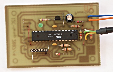
The complete circuit without LCD display
Using the I2C communication
Download (see references) the
linuxI2Ctemp tar.gz file and unpack it. The I2C communication is
implemented in 2 files:
i2c_avr.c -- the i2c statemachine for the atmega8
i2c_m.c   -- the complete i2c protocol on the linux side
I have given the atmega8 the slave address "3". To send the
string "hello" to the atmega8 you would execute the following C
functions:
address_slave(3,0); // tell the slave that we will send something
i2c_tx_string("hello");
i2cstop(); // release the i2c bus

on the microcontroller side you would receive this "hello" string with
i2c_get_received_data(rec_buf);
Very easy. Reading data from the microcontroller is similar.
Look at the file i2ctemp_avr_main.c to see how it works when the
temperature readings are done.
How warm is it?
To compile and load the code for the
microcontroller run the following commands from the linuxI2Ctemp
package directory.
make
make load
Compile the two programs i2c_rs232_pintest and i2ctemp_linux
make i2c_rs232_pintest
make i2ctemp_linux
... or just use the pre-compiled versions in the "bin"
subdirectory.
To read temperatures simply run:
i2ctemp_linux
... and it will print indoor and outdoor temperatures. To
make this data available on a website I suggest to not directly run
i2ctemp_linux from the webserver because the i2c communication is
very slow. Instead run it from a cron job and write from there to a
html file. An example script is included in the README file of the
linuxI2Ctemp package.
The LCD display
For the LCD display we use a HD44780
compatible display as it was already used in previous articles.
These displays are very easy to use in combination with
microcontrollers because you can send them ASCII characters.
I use the same LCD driver code as in all previous articles. The
files which implement this LCD driver are lcd.c lcd.h and
lcd_hw.h. They are in the package which you can download at the
end of this article. The interface for this code is really easy
to use:
// call this once:
// initialize LCD display, cursor off
lcd_init(LCD_DISP_ON);

// to write some text we first clear
// the display:
lcd_clrscr();
lcd_puts("Ok the LCD");
// go to the second line:
lcd_gotoxy(0,1);
lcd_puts("works!");
The software is written such that it works with both 16x2 and
20x2 LCD displays.
There is also a test-lcd.c program which can be use to test the
LCD display. After loading the corresponding test-lcd.hex file
into the microcontroller you should see "=OK=" on the display.
The complete circuit with LCD display
The LCD display has a contrast pin. Connecting this pin to GND results
in maximum darkness of the display. The total darkness off the display
depends however very much on the make of the display, the viewing angle
and power supply voltage level.
A change of 0.2V results already in a noticeable change of display darkness.
In most cases it is quite OK to connect the "CON" pin directly to GND.
If that gives however a too dark display then add a voltage divider as
shown here:
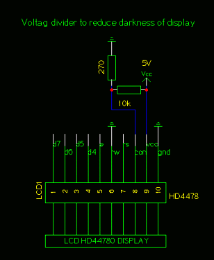
Since the CON pin is normally directly next to the VCC pin the
easiest solution is to solder the 10K resistors directly to the display and
insert the 270 Ohm resistor in the wire that goes to the CON pin.
A little GUI
For those wo would like to have GUI on their
desktop I made a really simple gui. It consists just of 2 labels
which are used to display the two line output of i2ctemp_linux
command (the i2ctemp_linux is the command which read the
temperatures from the circuit via I2C):

Now we have a really cool thermometer. With a lot of
possibilities:
- You can read the temperature locally from the display
- You can have a little GUI on your desktop
- You can write values with a cronjob to a log file to get
long term statistics
I will now use the rest of this ariticle to explain a bit
the internals of the software.
Makeing temperature data available on the web
You should
not run i2ctemp_linux directly from the webserver. It is too
slow. Instead add a contab entry which runs a script to generate
an appropriate webpage e.g every 15 minutes:
The script to run from contab:
#!/bin/sh
webpagefile=/home/httpd/html/temp.html
echo "<h2>Local temperatures</h2><pre>" > $webpagefile
i2ctemp_linux | sed -e 's/i=/inside  /;s/o=/outside /' >> $webpagefile
echo "---------" >> $webpagefile
date >> $webpagefile
echo "</pre>" >> $webpagefile
Copy the i2ctemp_linux program to /usr/bin and run the above
script e.g from a crontab entry which looks like this (load a file
containing this line with the command crontab):
1,15,30,45 * * * * /the/above/listed/scriptfile
How it works: Analog to digital conversion
The Atmega8
supports two modes. In the continous mode it permanently measures
the analog signals and just triggers an interrupt when the
measurement is ready. The application software can then use this
interrupt to quickly copy the result from two registers into a
variable.
The other mode is the so called single shot mode. Here only one
conversion is done. The single shot mode is still pretty fast.
Including the setup time of the required registers before and the
reading out you can still get 100 conversion per second. This is
more than fast enough for us. So we use this mode because it is
easier to use in functional programming. We just call a function
and it returns the ADC values.
The Atmega8 has analog input pins ADC0 to ADC3. In addition to
this there are the pins AGND (analog ground, connected to normal
ground), AREF (the reference voltage) and AVCC (connected to
+5V).
During analog to digital conversion the analog signal is compared
with AREF. An analog signal equal to AREF corresponds to a
digital value of 1023. AREF can be any external reference between
0 and 5V. Without the use of an external reference you can still
do precise conversion by either using an internal reference
(2.56V) or AVCC. What is used is decided in the software via the
REFS0 and REFS1 bits in the ADMUX register.
The analog to digital converter can convert one of the input
lines ADC0-ADC3 at a time. Before you start conversion you have
to set bits in the ADMUX register to tell the chip which channel
to use.
A simple analog to digital conversion would then look like this:
unsigned char channel=0; // measure ADC0
int analog_result;

// use internal 2.56V ref:
ADMUX=(1<<REFS1)|(1<<REFS0)|(channel & 0x0f);
// ADCSR: ADC Control and Status Register
// ADPS2..ADPS0: ADC frequency Prescaler Select Bits
// ADEN: Analog Digital Converter Enable, set this before setting ADSC
ADCSR=(1<<ADEN)|(1<<ADPS2);

//  start conversion
ADCSR|= (1<<ADSC);
while(bit_is_set(ADCSR,ADSC)); // wait for result
adlow=ADCL; // read low first !!
adhigh=ADCH;
analog_result=((adhigh<<8)|(adlow & 0xFF));
As a software designer you must watch out that you read the
lower 8 bits first as the microcontroller has some locking
mechanism to simulate "atomic" reading. After this we have the
analog to digital conversion result available as a number in the
analog_result variable. This can the be used elsewhere in the
program. Very easy.
The ADPS register (ADC clock pre-scaler bits) must be set such
that the clock frequency divided by the pre-scale factor is a
value between 50 and 200 KHz. The division factor is 2^ADPS (two
to the power of the ADPS bits value). The above setting (ADPS2=1,
ADPS1=0, ADPS0=0 = decimal 4 -> 2^4 = 16 -> division factor
= 16) is good for a clock frequency of 1MHz.
The Atmega8 has several possibilities for reference voltage
selection. The reference voltage is compared against our analog
input voltage. It is the voltage that corresponds to a digital
value of 1023.
| REFS0=0, REFS1=0 |
use external AREF, Internal Vref turned off |
| REFS0=0, REFS1=1 |
AVCC with optional external capacitor at AREF pin |
| REFS0=1, REFS1=1 |
Internal 2.56V Voltage Reference with (optional) external
capacitor at AREF pin |
An optional capacitor on the AREF pin can be used to
suppress noise and stabilize the AREF voltage (in case you switch
between differnt voltage levels: remember that it needs time to
charge the capacitor).
How it works: I2C communication, Atmega8 part
I explained
already in the beginning of this article how this I2C protocol
works. Let's now have a look at the software. The Atmega8 has
hardware support for I2C communication. Therefore you do not
actually need to implement the protocol. Instead you need to
implement a state machine. This tells the Atmega8 what to do
next. Here is an example:
An I2C packet with our own slave address was received. The
Atmega8 will now call the function SIGNAL(SIG_2WIRE_SERIAL) with
the status code 0x60 (for other events we would get other
codes).
--> We must now set a number of registers to tell the Atmega8
what to do next. In this case we will tell it: receive the data
part and acknowledge it.
When the actual data was received we will get called with status
code 0x80.
--> Now we read the databyte and tell the Atmega8 to
acknowledge the next data byte if it comes.
When the communication is over we get a status code 0xA0 (stop
condition) and we can tell our application that a complete
message was received.
The whole state machine for the I2C slave mode and all possible
states are explained in the datasheet of the Atmega8 on page 183
(see link in reference section at the end of the article).
Transmitting data is very similar. Have a look at the code!
How it works: I2C communication, Linux side
First a word
about the hardware. Even though I2C is a bus we only use a point
to point connection between one slave and the Linux PC as I2C
master. We can therefore save the pullup resistor as long as the
slave can still pull down the line without causing a short
circuit. We just put a 4.7K resistor into the line.
The voltage levels must be adjusted. The voltage levels on the
RS232 side are +/- 10V. This would be too much for the Atmeag8
but it has also an internal over voltage protection diode. We
limit with the 4.7K resistors the current so much that it is
sufficient to relay that protection diode for over voltage
protection.
The Linux I2C software implements basically a complete I2C stack.
This is because I wanted to have a little command line utility
which does not need any special library or kernel module. It
should just work on its own.
If you look into the file i2c_m.c (see download) you can see that
really every I2C message is build bit by bit.
To generate the "bits" we must toggle the physical pins on the
rc232 interface. This is done with ioctl calls:
        // set RTS pin:
        int arg=TIOCM_RTS;
        ioctl(fd, TIOCMBIS, &arg);
... or to produce a zero:
        // clear RTS pin:
        int arg=TIOCM_RTS;
        ioctl(fd, TIOCMBIC, &arg);
If you want to port this stack to a different OS then you
just change these lines. The rest is plain C and independent of the
operating system.
How to mount the outdoor sensor
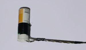
The
outdoor sensor must be protected properly against rain (and sun).
You can try to wrap it into some plastic but I don't recommend
this. No matter how tight you tie it, water will eventually come
in and stay in there. The NTC is quite robust and it does not
matter if it gets a bit humid as long as it can dry again. Use a
up-side down mounted tablet tube which you leave open at the
bottom. This way any water will be able to get out again.
Conclusion
I am now using the thermometer for 2 years and
I really like it because you can read it out directly on the
display and you have the possibility to store all the data on
your PC. You can view it there, draw graphs do statistics. Really
cool.
The I2C protocol requires very little extra hardware and is
optimized for transmitting or receiving small amounts of data.
That is exactly what we need when we want to communicate with our
own microcontroller hardware. It is really a very nice
solution!
References
© Guido Socher, tuxgraphics.org
2007-05-14, generated by tuxgrparser version 2.55