home |
electronics |
toolbox |
science club |
tuxtalk |
photos |
e-cards |
online-shop

An AVR microcontroller based Ethernet device
![[Illustration]](../../common/images2/article06061/articletitle_th.jpg)
Abstract:
Ethernet has traditionally been a quite complex interface. All Ethernet
chips until today had 100 pins or more, where difficult to find in small
quantities and difficult to use from a small microcontroller with little
memory. Microchip has changed the world with their new ENC28J60 Ethernet chip!
The ENC28J60 is a small chip with 28 pins only and has a SPI interface which
is easy to use from any microcontroller.
This opens a whole world of completely new applications. You can easily build small
devices which can be spread all over the house and simply connected to ethernet.
You don't need anymore a separate serial connection or other bus. Everything
can be easily connected via Ethernet. Distance is no longer a limiting factor.
Even WIFI connectivity is possible because you can connect the devices to a
wireless bridge.
All hardware components are available from shop.tuxgraphics.org.
The software and circuit diagrams are available for free (GPL V2 license).
_________________ _________________ _________________
|
Introduction to the ENC28J60 Ethernet controller
The ENC28J60 from Microchip is a fantastic chip. It has Tx/Rx, MAC and PHY in one small chip.
There are very few external parts. Basically just a crystal and an Ethernet
transformer, aka magnetics. All this comes in an convenient 28-pin DIP package. Easy
to solder and perfect for hobby applications.
Figure 1: Schematic block diagram.
The microcontroller can then control any hardware you like: You can
attach some sensor (light, temperature), you can switch on an off something
you can attach a LCD display, etc...
The Plan
In this first article we will build a generic hardware with lots of IO
interfaces and analog to digital converter inputs. We will however only
control a small relay to switch on or off something. In later articles
we can then use the same hardware and do more complicated things.
The main purpose is to show here the circuit diagram and explain the software.
We use a UDP application to send commands to the microcontroller. Those commands
will then cause the microcontroller to switch on or off the relay.
It think it will be possible to even implement TCP. The current UDP software is
less than 3k bytes and that is not even half of the memory on an Atmega88.
TCP would then allow us to control the device via a web browser. I have however
not tried it yet.
The circuit diagram
Here is the circuit diagram. Most of it is very straight forward and standard
for the ENC28J60. The polarity of LED-B is important as it determines the duplex
operation of the chip. Standard Half-duplex is what makes most sense for a
device which will send and receive only rather little traffic.
Figure 2: Circuit diagram (click on the drawing to get a printable pdf version). The circuit diagram of the previous hardware version can be found in the download section
A relay can be connected to connector CONN3.
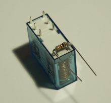
Note the diode D1. It is not useless and it is not the wrong way round in the
circuit diagram even though it looks like that. It is there for those who plan to
connect a small 6V relay on that output. It protects the whole circuit against the
possibly very high voltages which can be induced by the coil of a relay.
If you use a relay with a large coil then you should also add a resistor in
parallel to the relay (e.g 1K or 2.2K). The diodes have a finite response time and
such a resistor will prevent the voltages to raise too fast before the diode
cuts them.
If you plan use 9V raw-DC (or maybe more) in combination with a 6V relay on CONN3 then you can add a small resistor (e.g 33 Ohm, you have to experiment) in series to the relay
to compensate for the higher voltages.
The connectors named "IO-ports" and "Analog-IN" are not used for now. They are
meant for future functionality which will be described in later articles. We
will only use CONN3 in this project.
Ethernet requires quite high currents because it can be used with rather long
cables. The above circuit consumes about 200mA at 3.3V. The LM2937-33 needs
therefore cooling if the supply voltage is more than 5V (on Raw-DC-In).
A small piece of aluminium is normally enough.
 |
 |
Filter coil L1
| Magjack: RJ45 with integrated
magnetics and LEDs |
Ethernet Magnetics and Filters
The ENC28J60 requires a transformer with a turn ratio of 1:1 certified for
10base-T. There are some very nice RJ45 connectors called "Magjack" which have
already integrated magnetics and optionally integrated LEDs.
In addition you need a small filter coil (L1 in the schematic). A 5mm ferrite
bead with 5-7 turns of thin wire seems to work well.
Hardware updates 2007
As of quarter one 2007 I have updated the hardware with regards to the following
points:
- The diode D1 was incorrectly connected against GND instead of Vdd.
Interestingly nobody noticed that fault. The wrongly connected diode was
protecting the transistor against negative voltages but not against voltage peaks induced by a relay coil.
If you did however follow my recommendation and use an additional resistor in
parallel to the coil then this one will keep already the current flowing through
the coil after power disconnection and it seems to be enough to protect the
circuit.
- The ENC28J60 has a clock output. I wanted to use it right from the
start but there was a problem with interrupted clock signals
at reset which caused sometimes the AVR to malfunction. I contacted microchip support about it but they did not seem to
understand the problem. Maybe microchip PIC controllers are
less sensitive to non continuous clock signals.
I finally figured out that it works if I do not use
both software and hardware reset during initialization of the chip. Now I use
just reset via software and that works well. The ENC28J60 can supply a 12.5MHz
clock signal. This gives a small speed increase over the 8MHz from the atmega88
internal clock. Atmel specifies that the atmega88 can handle
0-20MHz @ 4.5-5.5V and 0-10MHz @ 2.7-5.5V.
This suggests that we should use max 10MHz but it
can't be a binary behavior starting suddenly at 2.7V. We can assume that it should be something between
10MHz and 20MHz. My tests show that 12.5MHz works stable and reliable at 3.3V.
If you did already build the previous circuit then don't worry. I will keep
any new software backward compatible with the old hardware. That is: the new
hardware will not run with the old software but the old hardware will run
with the new software. There is also no
real need to modify or update your existing hardware. Never change a running
system! For those who would like to look at the old circuit diagram from 2006 can find
it
in the download section.
Step by step: Assembly and testing
A problem of all microcontroller based electronics is that it is difficult
to develop for the first time. Usually nothing works for some reason and
then the big question is where are the errors. Errors are usually made in
both software and hardware. You have the advantage that
you have already a reliable base. You know at least that the software works
and that the circuit diagram is correct because you can base on my work.
Still it makes sense to build the hardware
step by step and test after each step. This way you can narrow down the
area of a possible fault.
Step one:
Solder the LM2937-33 voltage regulator and the needed capacitors onto the board.
Connect Raw-DC-In to a 5V lab power supply and use a voltage meter to
check that the output is 3.3V. Now take a small 3.5V torch bulb or a 6V bicycle
bulb and connect it also to the output. Check that you have still 3.3V with
a little bit of load.
Step two:
Solder the ENC28J60, the magjack and all other parts around the ENC28J60 on
the board, but not the Atmega88 microcontroller.
Connect the circuit again to 5V power on Raw-DC-IN (limit the current to about 300mA,check that you get again 3.3V).
Now connect an Ethernet cable from you Hub or Switch to the circuit.
The green LED on the Magjack should go on and stay on. The link LED on your
Hub/Switch should also go on.
Ethernet has a pulse based link negotiation protocol (FPL, Fast Link Pulse).
The green LED indicates that this link negotiation works and was successful.
Step three:
Solder the Atmega88 onto the board. Power the circuit up again.
Unpack the eth_rem_dev-1.X software (download at the end of the article)
and run the command "make test0.hex" from a shell. This will compile the
test0.hex file. Load this file into the microcontroller (e.g. with "avrdude -p m88 -c
avrusb500 -e -U flash:w:text0.hex" or use the make target "make load_test0"). If you have
one of the tuxgraphics programmers then you can just type "make load_test1"
under Linux.
Note that Atmega88 needs at least avr-glibc-1.4.X.
This will cause the red LED (D2) to blink with 1Hz.
Now we have checked all major components of the circuit and there is a
good chance that it will work with the final software.
I have used during my development also some more test programs which are
included as well in the eth_rem_dev-1.X package.
- test1: Allows you to ping the circuit
- test2: Sends a string back
All of them are described a bit more in the README file of the
eth_rem_dev-1.X package. You can use them also as example programs for your
own development.
The last step:
Edit the file main.c and change the 2 lines:
 static uint8_t mymac[6] = {0x54,0x55,0x58,0x10,0x00,0x24};
 static uint8_t myip[4] = {10,0,0,24};
For the first device you build you will not need to change the mymac line.
But you will probably need to change the IP address (myip). It must be a
free address from the address range in your network.
There is a range of private addresses (not routed on the public Internet)
which you can use:
Netmask         Network Addresses
255.0.0.0       10.0.0.0 - 10.255.255.255
255.255.0.0     172.16.0.0 - 172.31.255.255
255.255.255.0   192.168.0.0 - 192.168.255.255
Example: your WIFI router might have 192.168.1.1, your PC might have
192.168.1.2. This means you could e.g use 192.168.1.10 and leave some
room for more PCs. If you use DHCP then make sure that the address it not
double allocated (exclude it from the DHCP range).
Now compile the software with the command "make".
Load the eth_rem_dev.hex file into the microcontroller and send your first
ping from a shell.
ping Ip.Addr.you.assigned
You should get a reply with 0% packet loss (stop the command with crtl-c).
Using eth_rem_dev to switch on or off something
The only supported useful function in the microcontroller code in this first release is to switch on or
off the transistor connected to PD7 (connector CONN3). More functionallity will
come later.
I have written a small program called udpcom which will send out a string
over UDP and wait for an answer string. udpcom is also included in the eth_rem_dev-1.X
package. The program is very small and should be
portable to many operating systems with minor modifications.
If you have ported the code to some not yet supported OS then send me the code
and I will include it in the next release.
To compile the udpcom command go to the directory eth_rem_dev-1.X/udpcom
and compile the right version of udpcom in one of the subdirectories
with the command "make".
The command to switch on is: t=1
The command to switch off is: t=0
Query the status: t=?
The syntax is: udpcom password,X=Y IP-addr
The default password of the eth_rem_dev-1.X is "secret". You can change it
in the same main.c file where you changed the IP address.
Here is an example:
./udpcom/unix/udpcom secret,t=1 10.0.0.24
II: data: secret,t=1, ip: 10.0.0.24 port: 1200
OK: 10.0.0.24: t=1

Now the transistor connected to PD7 should be on and if you have a relay
connected to that transistor the relay should be on too.

./udpcom/unix/udpcom secret,t=? 10.0.0.24
II: data: secret,t=?, ip: 10.0.0.24 port: 1200
OK: 10.0.0.24: t=1

Here we query the status and the answer "OK: 10.0.0.24: t=1" indicates that
the transistor is "on".

./udpcom/unix/udpcom secret,t=0 10.0.0.24
II: data: secret,t=0, ip: 10.0.0.24 port: 1200
OK: 10.0.0.24: t=0

Now the transistor connected to PD7 should be off again.
The ready build Ethernet remote switch device
Here two photos from the device which I have built.
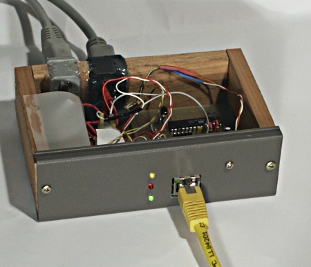
Front view with box open: You can see the two LEDs above the Magjack
and 3 additional ones. Green is for power on, red changes when a UDP packet is
processed, yellow indicates the current state of the relay (on or off).
The connectors on the back are power and relay out. Under the white plastic
cover on the left is a small 9V switched power supply circuit.
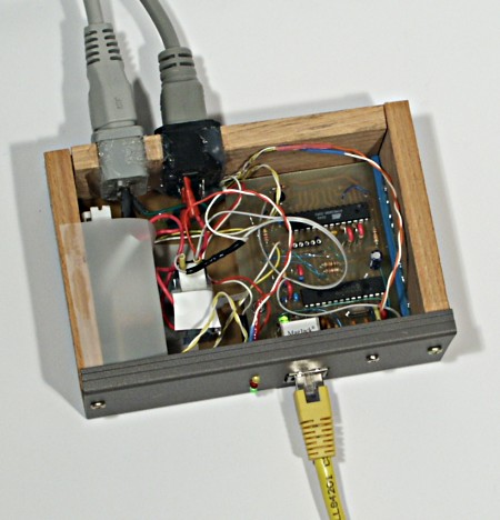
Top view with box open: You see the little Ethernet board on the right with
the microcontroller. Left are (insulated and not really visible): relay and power
supply. The LM2937 is mounted with a single screw on the grey aluminum front.
The sides are wood and top/bottom of the box are plastic.
Software structure
Before we look at the software on the microcontroller
we should study how network socket programming works under Linux.
On the microcontroller side we can (and have to) build every bit
of the Ethernet frame. Under Linux (or any good OS) we are in a
much more civilized environment and can't just do what we want.
A host has one Ethernet address (MAC address) per interface and one
or more IP addresses per interface. Those MAC addresses are world wide
unique but this is just to make the hardware distribution easier.
They just have to be unique in your local environment. That is: Your PCs,
your (WIFI) router and the router of your internet provider have to have
distinct MAC addresses.
The network applications on the host are then distinguished by port numbers.
Only one port number can be active at a time. That is: you can not have
two web servers running on port 80 on the same host. When you send a message
then a local (random) port number is allocated and the request is sent to the
remote IP and well know port number (e.g 80=web).
If you have an application process listening on port X locally for connections
(server) then you can not start a second application sending on the same port.
However the same program can send and receive on the same port.
The port numbers below 1024 are reserved numbers.
We just pick a port number: 1200
PC network interface           AVR Ethernet device
MAC1,IP1 src.port=34256 --> MAC2, IP2 dest.port=1200

                        Answer:
MAC1,IP1 dest.port=34256 <-- MAC2, IP2 src.port=something(e.g 1200)
UDP is unreliable?? That is not really true. On a local LAN there is almost
no packet loss unless you have problems with the hardware duplex configuration but that
is a different problem and should be fixed asap. The packet loss ratio on a
local non congested LAN is
better than 10EE-9 or one in 100000000. With normal home traffic volumes on a
24/7 Linux network that is far less than one packet per month.
UDP is on a local network very reliable and all that it means is that we must
be able to resend the data without causing harm.
We must not implement a "toggle" switch but one command to switch on and one to
switch off. If we re-send the on command (because it was lost) the result will
still be "on". That's all.
I will list now the names of the AVR microcontroller source code files that way you can easier
change and modify things:
main.c -- all execution starts here. It starts all initialization and has
          also the main loop.

enc28j60.c, enc28j60.h -- enc28j60 hardware dependent things

net.h -- networking constants, byte positions, headers

ip_arp_udp.c, ip_arp_udp.h -- IP, ARP, ICMP and UDP stack functions

traffic.txt -- Full decoded messages of the communication, taken with a
               network analyser. This makes it easier to understand what
               is going on in the code.
Filters
As your can imagine there is the problem that Ethernet can supply much
more data than that little microcontroller can process over the serial SPI
interface even if that interface runs with several MHz speed. There is a
buffer in the Ethernet controller but it could fill up
easily with garbage on a noisy Windows network. The ENC28J60 has therefore
filters.
The traffic we want is: UDP traffic with the destination of our MAC address.
On top of that we have to process ping (IP/ICMP packets for our MAC address)
and ARP packets to our MAC or to broadcast. No IP
networking is possible without ARP.
All other packets, especially broadcast IP packets can be ignored. The
ENC28J60 has a number of simple filters which we will use for this.
There is an uni-cast filter (only packets with our MAC as destination).
The only other packets we want are broadcast ARP. There is packet match
filter and we program it to destination MAC=FF:FF:FF:FF:FF:FF (broadcast) and
only Ethernet content-type=ARP. This is done during the initialization in the
file enc28j60.c.
Conclusion
This small Ethernet remote device opens a completely new world of
fantastic applications. It's small, it's easy to build and there are endless
possibilities to use it.
The communication is fast! There is no
delay between the sending of the command and the answer. That is
very different from RS232 at standard 9600 baud as used for most
microcontroller communication.
I found it really exciting to build this hardware and make it work.
It is a simple switch on/off application for now but the circuit
has all the IO-ports already prepared to do more.
A note on security
If you plan to switch main-power (230V or 120V) with the relay then
get good heat shrink tube and insulate things such that you can't touch
any mains carrying parts even if the box is open. It's saver for you and
all the equipment on your network.
Download and links
© Guido Socher, tuxgraphics.org
2008-08-03, generated by tuxgrparser version 2.55